 ZORGON (jiangsu) Automation Technology Co., Ltd.

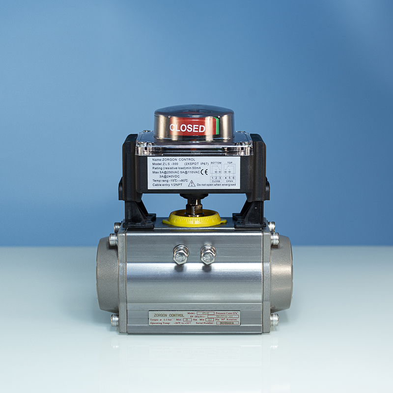
Pneumatic valves are more and more widely used in various professions, and the skills of pneumatic actuators are getting better and better. The gap between domestic pneumatic actuator and imported pneumatic actuator is getting smaller and smaller, and the types are getting more and more.
1.Fix the pneumatic actuator on the calibration platform, connect the air source, control the air source and displacement detection connecting rod; Accurately adjust the instrument on the calibration table;
2, mechanical zero calibration: input 4mA current signal (0%), control gas signal should be 0.02Mpa, at this moment the cylinder piston stroke should be zero; If it is not zero, it can be adjusted by adjusting the nut on the zero conditioning screw to adjust the zero (zero) and tighten the nut); Zero point and range requirements repeated adjustment; Zero error should be less than 1%;
3, mechanical full scale calibration: input 20mA current signal (100%), control gas signal should be 0.10Mpa, at this moment the cylinder piston stroke should be the upper limit; If it is not the upper limit, the tension adjustment scale of the tension spring can be adjusted (the tension scale is small when the tension spring is loose, and the tension scale is large when the tension spring is tight); Zero point and range requirements repeated adjustment; The full scale error should be less than 1%;
4, mechanical range midpoint positioning: after the zero and range adjustment, input 12mA current signal (50%, 0.06Mpa), adjust the orientation of the connecting rod of the azimuth transmitter, so that it is perpendicular to the horizontal plane at this moment;
5, full stroke error calibration: input control gas signal 0.02Mpa(0%), and then gradually increase the input signal 0.036Mpa (20%), 0.052Mpa (20%), 0.068Mpa (60%), 0.084Mpa (80%), 0.1Mpa (100%), Make the cylinder piston travel completely, and the error at each point should be less than 1.5%;
6, nonlinear error test: input control gas signal 0.02 mpa(0%), then gradually increase the input signal to 0.10 mpa(100%), and then reduce the signal to 0.02 mpa(0%) actuator to complete the stroke, stroke and recorded value increased and decreased by 0.008 accordingly mpa pressure signal, the relationship between the nonlinear error and the theoretical value of the practical compression stroke should be less than 1%; does
7, positive and negative stroke change test: the same as the nonlinear error test method. In the practice of positive and negative pressure stroke relationship, the difference between positive and negative stroke values of cylinder piston under the same pressure value should be less than 1%;
8, sensitivity test: increase and decrease the pressure when the signal pressure is 0.03, 0.06, 0.09Mpa stroke. Test the required signal pressure change value when the cylinder piston rod starts to move 0.1mm, the change should be less than 0.2%;
9. Piston cylinder tightness test: Connect 0.5Mpa pressure with any air chamber of the cylinder, and then cut off the air source. Within 10 minutes, the pressure drop in the cylinder should not exceed 0.01 Mpa
10, azimuth transmitter electrical zero check: open the azimuth transmitter cover, connect the wire; Input 12mA current signal (0.06Mpa), adjust the circular eccentric inside the transmitter, so that the black line and the line above the black line are aligned with the white line on the board; Then input 4mA current (0.02Mpa), now can adjust the zero potentiometer in the transmitter to make the output current 4mA; Electrical zero error should be less than 1%;
11, azimuth transmitter full range detection: input 20mA current signal (0.1Mpa), at this moment can adjust the transmitter internal potentiometer, so that the output current is 20mA; Electrical full range error ≤1%;
12, full stroke azimuth response current error calibration: Input 4 ma current (0%), and then gradually increase the input signal 8 ma current (25%), 12 ma current (50%), 16 ma current (75%), 20 ma current (100%), taking into account the nonlinear error conversion from the linear displacement Angle change, the reaction current error of 0%,50% and 100% points should be ≤1%, and the reaction current error of 25% and 75% points should be ≤2%;
13, manufacturing verification records, according to the verification record form carefully filled in, and signed by the inspector;
14, after the completion of the above test, the pneumatic actuator should insert the terminal into the azimuth transmitter, tighten the back cover, and then insert the plastic plug into the valve positioner air source inlet.

CONTACT
Enter your Emall or phone number and we will contact you as soon as possible. ZORGON As a professional automatic control equipment manufacturer in the UK, with the first solenoid valve came into being, after decades of continuous innovation and development. With the transfer of...
 Any question or request?
Click below, we’ll be happy to assist. CONTACT